Understanding precision agriculture
INTEGRATING SOIL, LANDSCAPE, AND YIELD MAPS
THIS ARTICLE IS the eighth in a series intended to introduce and explain the concept of management zones, to provide a process to define, delineate, and characterize management zones, and to outline the kinds of data and computer tools needed to be successful (go to www.gfo.ca/research/ precisionag to read previous articles you may have missed).
The integration of various data layer maps results in a management zone map. The intent of this article is to offer a method of integrating the base layer maps to create and characterize management zones.
A cash crop field located near Guelph will be used as an example. This management zone could be defined as a two acre area in a field that has a Guelph loam soil type on upper and mid slope positions, that consistently produces high and above average yields for all crops and faces southwest. This zone has an average topsoil depth of 25 – 30 centimetres, an average slope of five per cent, some surface stone, an average pH of 7.0, and three per cent organic matter.
CREATING A MANAGEMENT ZONE
The process of creating management zones involves the intersection of various data layer maps (such as soil, yield index, and elevation maps) which have been detailed in previous articles.
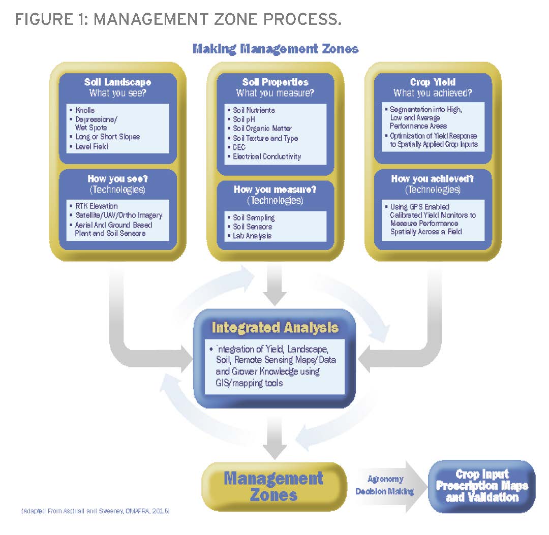
Various layers may be available for this integration process. As an example, the following assumes the availability of a yield index and detailed soil map.
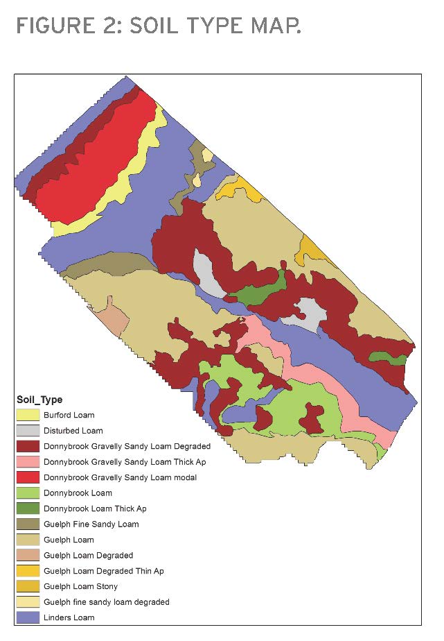
A predictive digital soil mapping (PDSM) method was used to create the soil type map shown in Figure 2. The data layers used included two terrain layers derived from the digital elevation model, an early September aerial image showing differential soybean maturation, and a suite of known soil types observed at selected points throughout the field. There were four soil series plus a disturbed soil mapped on this field. A number of soil phases for the Guelph and Donnybrook soil series were identified and mapped as well.
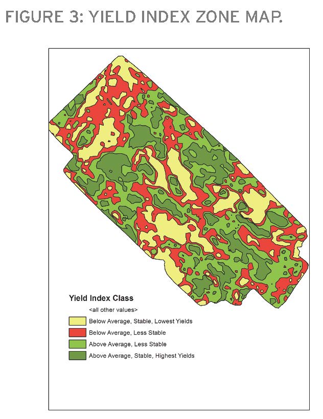
The yield index map is shown in Figure 3. This map was created from seven years of yield data (four years of winter wheat and three years of soybeans). Four yield index zones are shown on this map. This map can be replaced with maps of the yield probability index, a SMS multiple year map, or a single year yield map.
If the producer does not have a detailed soil map or a yield map and still wishes to break his field into meaningful zones, a segmented aerial image, a NDVI map, or a convexity/concavity (knolls and depressions) map derived from a digital elevation model can be used. To add a soil component to the zones defined, the producer’s knowledge of the field can be used to assign a soil texture class (sandy, loamy, or clayey) to each zone.
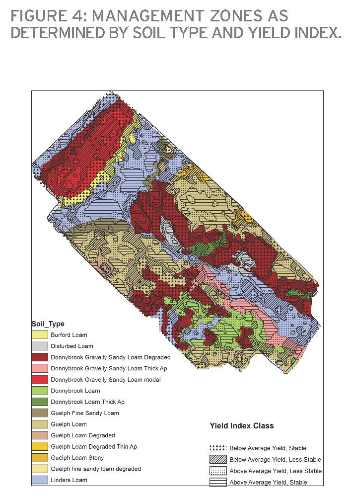
Figure 4 shows the management zone map created by intersecting the yield index and soil type maps. Note that there are a number of very small polygons which you may decide are too small to be managed separately and the software can incorporate these into adjoining zones to accommodate equipment size and other factors.
A rule of thumb is to calculate a minimum area by squaring the width of the planter (for example, a 16 row planter has a width of approximately 12m (40ft) which equals an area of about 144 m2 (1600 ft2)) as a minimum zone size. Most people are not yet prepared to manage a field at this resolution and choose to combine similar polygons together to make larger management zone units.
The zones can be characterized in terms of average yield over time. Three management zones are identified in Figure 4:
• Guelph loam with stable above average yield over time
• Donnybrook gravelly sandy loam — stable, below average yield over time
• Linders loam — stable, above average yield over time.
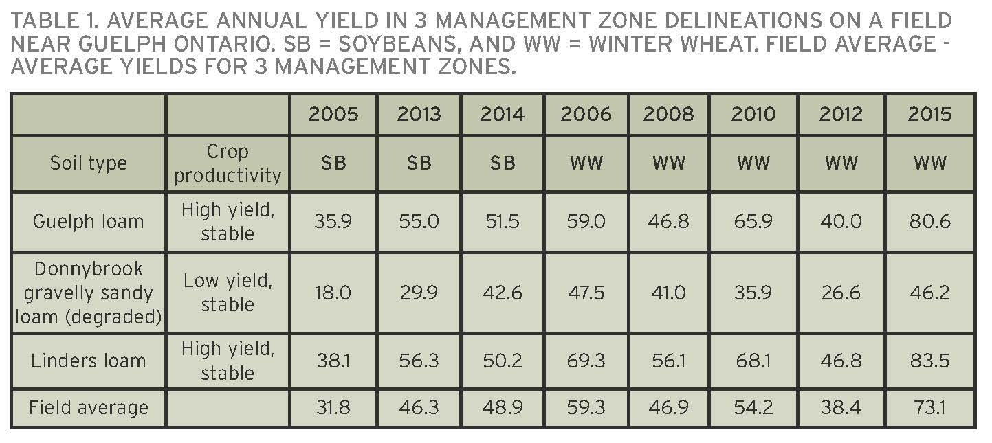
To further quantify how distinctly different these zones perform over time, Table 1 provides the absolute average yields (bushels/acre) for each of these management zones by crop year.
Using a grid sampling strategy, soil fertility samples were collected and analyzed for per cent organic matter (%OM), pH, phosphorus (P), potassium (K), magnesium (Mg), calcium (Ca), Zinc (Zn), manganese (Mn), and cation exchange capacity (CEC) among others. A dense grid sampling was done only used to get a systematic perspective of the field in the first attempt to acquire soil fertility base data. Once reliable zones are developed, a zone sampling strategy should be implemented going forward.
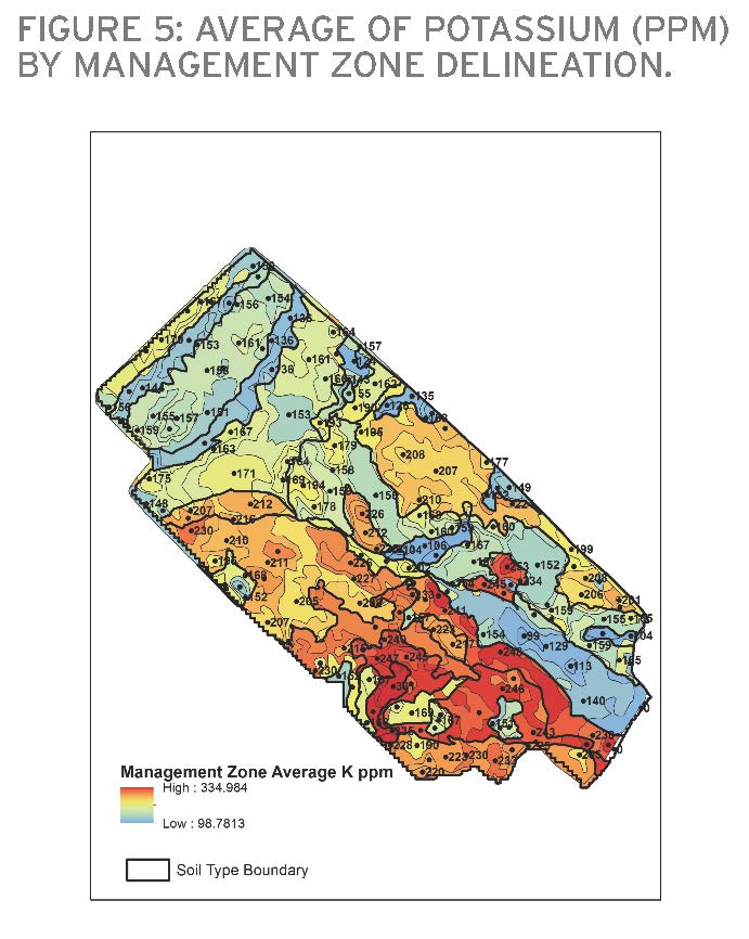
A map showing the average value of each parameter for each management zone was created using PDSM mapping tools. Input layers included the management zone map, the red, green, and blue bands from the September 4, 2013 google satellite image, and the analytical results for 62 soil samples. A map of the average K in parts per million (ppm) per zone is given in Figure 5. The black dots mark the center point for each management zone polygon and the number displayed next to the dot is the average value of K ppm within the polygon.
MANAGEMENT DECISIONS
A summary of the soil, landscape, and yield index management zone characterization factors for three selected management zones is given in Table 2. The kinds of information embedded in this table will be useful for making management decisions.
Relative slope position is scaled from 0 – 1 and is used to indicate if a point in the landscape is located in an upper (1), mid (.5) or lower slope (0) position. The LS factor is a combination of slope length and slope gradient and is used here as indication of the potential for soil erosion to occur. The topographic wetness index (TWI) is used to indicate where soils are more likely to be wet.
In the Linders Loam management zone you can understand why this zone produces so well consistently year after year. This zone holds the most moisture because it is a relatively level region (two per cent slope), located at the low end of the field (337 metres) where is receives a consistent supply of water due to the landscape position. It has the lowest susceptibility to erosion due to precipitation events, wind, or tillage practices (lowest LS factor). This zone could potentially be managed more intensively; for example, it could be a good candidate for a higher seeding rate on corn.
SUMMARY
This field near Guelph provides a good example of why a highly detailed soil type map explains the impact on crop performance. The soil type falls in a distinctly different part of the agricultural landscape. Each of these zones also exhibit different soil chemistry, which in combination with the latter two factors should result in different management decisions for crop inputs.
This certainly is the ultimate version of a stable, reliable management zone map that lends itself to a very comprehensive precision agriculture strategy. Extensive data collection, soil coring, and sample analysis occurred in conjunction with soil science expertise. The decision to attempt to complete this extensive investment in one farm field depends on the capacity of the farming operation and the management goals defined. If this investment, time, and integrated analysis of a multi-layer dataset is completed, rest assured it will last a lifetime.
The integration process used in this article to develop the Management Zone Map used the following software tools: ArcMap 10.2 (ESRI), SAGA, SoLIM Solutions 2010, Vesper 1.6 (the final three being free software). Other products being used commercially by precision agriculture specialists include Farmworks, SMS, SST, and others. The software continues to evolve and become more sophisticated and user friendly. Many service providers are proficient in the use of many of these tools.
The next and final article in this series will discuss in more detail what crop input prescription maps can be made using these management zones. It will also explain how automated validation can be placed within a management zone to test if the right rate of seed or fertilizer has been implemented. •
